Internet of Things – Testboard
IoT (Internet of Things) can be explained by connecting „stupid“ sensors or devices to the internet and make them controllable over network. Being able to access them from everywhere on the net offers a wide range of applications.
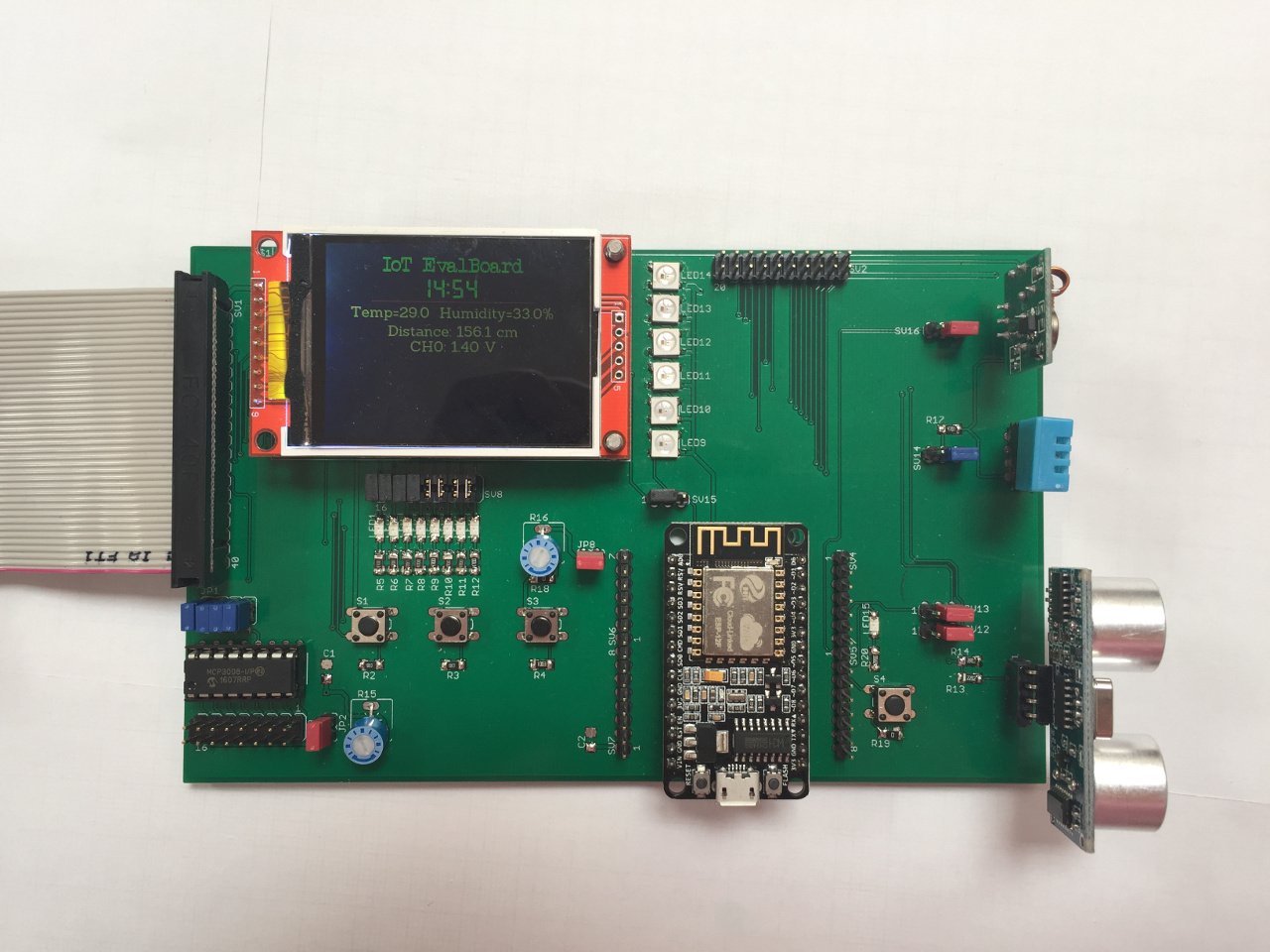
This testboard helps you to get quickly started into the wide field of IoT. It uses some of the most popular sensors and devices available.
The board can be used with a Raspberry Pi (2,3, Zero, Zero W) or with an ESP8266 module. Both modules can be attached to the testboard at the same time. When using both modules it is possible to build up a kind of Client/Server architecture.
Testboard Specifications:
- Raspberry Pi connector
- ESP8266 Module
- Display 2.2″ (320×240 pixel)
- Analog-Digital Converter (MCP3008)
- 9x LED
- 4 Push-Button
- 6x WS2812b RGB-LED
- Ultrasonic distance sensor
- DHT11/22 Temperature-Humidity sensor
- DS18b20 Temperature sensor
- 433Mhz Transmitter
- access to unused GPIO via Pin-Header
You can use any language you like for coding and playing around with this board. In my examples I will use Python to show you the basics (and advanced topics as well) of IoT.
Things you can learn with this IoT-Testboard:
- digital output (Raspberry and ESP8266)
- digital inputs (Raspberry and ESP8266)
- analog input (Raspberry and ESP8266)
- controlling a digital output with a PWM-Signal (PulseWidthModulation)
- I2C / SPI
- 1-Wire sensor
- and and and
Before we can start using the board we need to have a look at the schematic diagram of the board. You can find it here: IoT-Testboard-Schematic
Continue reading my blog to find tutorials that can be done with the testboard. Most of the tutorials can also be used without the board. (in this case you will have to adjust some settings e.g. GPIO Pin, …. in the provided Python examples).
Tutorial: Raspberry Pi – GPIO